Hotline:
0755-86068609

Publisher:Administrator Date in:2019-01-24
What is a relay? What is the use and principle of relay: relay is an automatic electrical appliance, which is suitable for long-distance connection and disconnection of AC and DC small capacity control circuits, and for control, protection and signal conversion in electric drive system. The input of the relay is usually current, voltage and other electric quantity, or non electric quantity such as temperature, pressure and speed. The output is the electrical signal or parameter change of the output circuit when the contact acts. The characteristic of relay is that when the change of its input value reaches a certain program, the output value will change step by step. There are many kinds of relays, such as voltage relay, current relay, electromagnetic relay, general relay, high frequency relay, power relay, signal relay and magnetic holding relay. Working principle of small relay electromagnetic relay is mainly composed of electromagnetic system, and figure t319 is the structure and symbol diagram of electromagnetic relay.
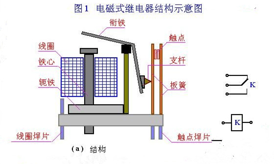
When the relay coil is energized with current, a magnetic flux loop is formed in the core, yoke, armature and working air gap D, so that the armature is attracted to the core by the electromagnetic attraction. At this time, the armature drives the strut and pushes the leaf spring away, so that one or several groups of normally closed contacts are disconnected (or the normally open contacts are connected). When the current of the relay coil is cut off, the electromagnetic force is lost, the armature returns to its original position under the action of the leaf spring, and the contact is closed again. In the circuit, when indicating the relay, just draw its coil and contact group related to the control circuit. The coil of the relay is represented by a rectangular box symbol, and the text symbol "K" of the relay is marked in or beside the rectangular box. There are two ways to express the relay contact: one is to draw it directly on one side of the rectangular box, which is more intuitive. The other is to draw each contact in its own control circuit according to the needs of circuit connection, which is beneficial for analyzing and understanding the circuit. However, it is necessary to note the same character symbol and number the contact group beside the coil and contact belonging to the same relay at the same time. Table b321 lists the common symbols of relays and the symbols of three contacts. According to relevant regulations, in the circuit, the drawing method of contact group shall be drawn according to the original state when the coil is not powered on.
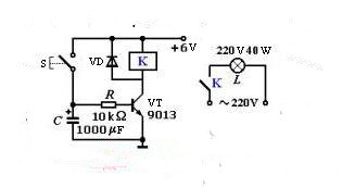
Figure T320 is a simple and practical automatic light off circuit. When the button switch S is pressed, the transistor VT immediately saturates and turns on. The power supply voltage (6 V) is applied to both ends of the relay coil to make it close. The moving contact is closed. The "220 V, 40 W" bulb power supply is turned on and lights up. At the same time, capacitor C is charged rapidly, so that its voltage at both ends is up to 6 v. When the button is released, the circuit providing current IB by the power supply is cut off, but there is voltage at both ends of capacitor C, which can also maintain the transistor operation. With the delay of time, the charge in the capacitor is discharged through resistance R and the emitter of the transistor, and the voltage at both ends of the capacitor decreases gradually. When the transistor Ube "0.5 After V, the VT is cut off, the relay coil loses voltage and releases, the contact is opened, and the power supply of "220 V, 40 W" bulb is cut off and goes out. This circuit, press the button switch s, the light will turn on for about 20 seconds and automatically turn off (the length of delay time can adjust the capacity of capacitor C), which can be used as the control device of corridor lighting. This example tells us that the relay can be used to control high voltage (220 V) and high current (hundreds of MA) circuits with low voltage (6 V) and low current (tens of MA). If we need to control higher voltage and current, we can use small relay to control large relay to improve the driving ability of the circuit. The diode VT in parallel with relay coil K is a protection diode, also known as a continuous current diode. As the inductance of the relay coil will generate high reverse voltage at both ends of the coil at the moment of power failure, this voltage will be superposed with the power supply voltage, and added between the transistors C and E, which is likely to exceed the maximum reverse breakdown voltage U (RB) CEO of the transistor, making the transistor breakdown damaged. The role of the diode VT is to eliminate the impact of this reverse voltage, and ensure that Protect the normal operation of the circuit. In electronic circuits, where there is a DC relay, a diode in reverse parallel with its coil is needed to prevent damage to circuit components.
Use the smaller current and lower voltage to control the larger current or voltage. More contacts, electrical isolation can also play a role in protecting the circuit! Generally used in communication, home appliances, automobile and other industries, the principle and base wiring diagram of commonly used small relays are DC type and AC type. Their shapes are the same. Their contacts are generally two groups of normally open, two groups of normally closed or four groups of normally open, four groups of normally closed. The corresponding sockets are also relatively uniform, but sometimes the printed numbers are not very clear, in order to make you clearly master them Corresponding to the wiring relationship, to prevent wrong connection, the electrical schematic diagram and physical wiring diagram are provided for your reference.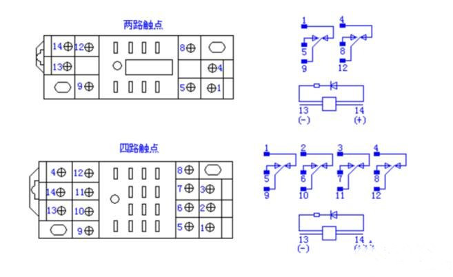
Note: for the relay with DC power supply working mode, terminal 14 shall be connected to the positive pole, and terminal 13 to the negative pole, so that the LED can be on, if it is connected reversely, it will not be on, of course, if it is connected reversely, it will also affect the action effect. For the relay of AC power supply, there is no polarity, and the diode must be on.
5-pin relay wiring method: Mark 30 (5-pin), 87 (4-pin), 85, 86, 87A (2-pin), 30 ground wire (batt normal power), 87 or 87A electric appliance, 30 and 87A are connected, 85 and 86 are both ends of a coil, 85 ground, 86 switch. 4-pin relay wiring method 4-pin marked 30, 87, 85, 86.30 and 87 are disconnected, 85 and 86 are both ends of a coil. 30 ground wire (batt normal power), 87 electric appliance, 85 grounding, 86 switch. Supply power to pins 85 and 86 of the coil, and pins 30 and 87 will be connected. The 3-pin relay wiring method combines 30 and 85 into one wire because they are all grounded. Shenzhen ouying Automation Control Co., Ltd. is a professional electronic component supplier, which has been focusing on the sales service and technical support of international first-class brand components. For more details, please contact customer service!